Quality assurance and testing procedures
The long professional career of Dr. Ing. Frank Wischnowski, the head of our QA facility, has turned him into one of the leading experts in the field of stainless steel in general and duplex steels in particular.
Our in-house laboratory is equipped with a large range of the latest testing equipment, allowing us to use various procedures to monitor and check the quality of our materials. We are therefore able to carry out virtually all destructive and non-destructive testing right here on the premises, in order to fulfil the requirements of our customers and of the different approval bodies involved. We can likewise determine quickly and competently, in the course of the corresponding material-development and damage-analysis procedures, such physical characteristics as chemical composition, microstructure, mechanical and technological properties, and resistance to corrosion.
If special investigative methods such as scanning electron microscopy, energy-dispersive microanalysis, x-ray diffractometry or wear and corrosion analysis are required, our teams of experts working under Dr. Ing. Frank Wischnowski and Dr. Ing. Tobias Simon collaborate closely with renowned research institutes and testing organisations.
Test methods
Tensile test in accordance with DIN EN ISO 6892-1
Category: Mechanical-technological and destructive testing.
Objective: Components are subject to mechanical stresses during operation. Tensile testing is used to determine various mechanical characteristics (such as modulus of elasticity and tensile strength) of a material. The structural dimensioning of components includes the establishing of strength specifications that steel must fulfil to withstand the strains that the item is subject to.
Testprinciple: A tensile-test sample (e.g. a 12 mm diameter bar) is held in place in the test apparatus, free of bending stress, and subjected to increasing tensile force until it begins to break. The apparatus keeps constant track, throughout the test, of the amount of force applied and the resulting change in length.
Evaluation/Result: These two sets of readings can then be used to generate a power/extension graph. The geometric details of the sample (initial cross-section and measured length) can be used to add meaning to the stress/extension graph.
This graph also allows us to identify such characteristics as modulus of elasticity, permanent elongation limit or yield strength, elongation at rupture and reduction in area when breaking. These readings are then compared with the stipulations of the applicable standard or the customer’s specifications.
Tensile test at temperature up to 900 °C in accordance with DIN EN ISO 6892-2
Category: Mechanical-technological and destructive testing.
Objective: Materials steadily lose strength as temperatures rise. Hot tensile testing is used to determine the strength of a material at high temperatures. It also allows certain material characteristics (e.g. modulus of elasticity, permanent elongation limit or yield strength, elongation at rupture and reduction in area when breaking) to be determined for a particular temperature.
Test principle: A work piece is clamped in the test apparatus, preheated to the desired temperature and then stretched at a constant temperature until fracture occurs. This determines the power required (as with tensile testing carried out at room temperature) as a function of the extension of the sample.
Evaluation/Result: The readings obtained are then compared with the stipulations of the applicable standard or the customer’s specifications, and the results are officially recorded in the corresponding material test certificates.
Charpy impact test at RT and low temperatures in accordance with DIN EN ISO 148-1
Category: Mechanical-technological and destructive testing
Objective: Charpy impact testing is used to determine the toughness of a material. “Toughness” describes how a material behaves when ruptured. A distinction is made between brittle and tough materials. Metals vary greatly in this respect, due to their different lattice structures.
With many steel alloys, notched-bar impact work also decreases as the test-temperature drops. Toughness is not an isolated property of the material concerned, but is decisively influenced by the shape of the sample and the way in which force is applied. The danger of a material failing due to brittleness is greatest when it is subjected to a triaxial state of stress (i.e. tensile stresses in all three spatial dimensions), in the form of an abruptly-applied load.
Test principle: A pre-defined V- or U-shaped notch is made in the sample in order to generate a triaxial state of stress. This sample is placed in a support located at the lowest point of the pendulum trajectory.
The pendulum ram used for impact testing possesses pre-defined potential energy. It follows a rotary downward trajectory upon being released, and strikes the rear of the notched sample at its lowest point. After splitting the sample, the pendulum ram continues its swing, but is now able to reach only a limited height.
The notched-bar impact work (Av) required to split the sample is based on the difference between the two potential-energy readings. Impact toughness is calculated with the help of the residual surface-area measured before rupture. Impact toughness is measured, during Charpy impact testing, with a trailing pointer attached to the test apparatus, or read directly by electronic means if an instrument-equipped pendulum configuration is used.
Evaluation/Result: A set of three impact-test samples is required to obtain a result for the notched-bar impact work. The notched-bar impact work is determined for each sample, and a reading calculated on the basis of their average value. The average for the three samples must exceed that of the (standard or customer-specified) notched-bar impact work. In the case of individual values, a sample may correspond to no more than 70% of the specified notched-bar impact work.
If the ductile-to-brittle transition temperature of a steel alloy is to be determined, this should be expressed as an Av-T diagram. This involves gradually lowering the test temperature, until the steel begins to show signs of brittle-fracture failure.
Brinell hardness test in accordance with DIN EN 6506-1
Category: Mechanical-technological testing.
Objective: The hardness of metals, and of steel alloys in particular, can be varied considerably by subjecting these materials to work-hardening and heat treatment. Hardness can, at the same time, allow certain conclusions to be drawn regarding the structural state of the material concerned, its suitability for machining and its resistance to wear.
Hardness is defined as the mechanical resistance of a material to penetration by another object. Brinell hardness testing provides a possible non-destructive method of estimating the tensile strength of steel.
Test principle: A spherical penetrating stamp is pressed into the surface of the test object for a defined period (10 to 15 seconds) at a specified pressure. The diameter of the spherical stamp, which depends on the thickness of the sample and the hardness of the material, can be taken from corresponding tables. Pressure on the spherical stamp causes plastic deformation of the material, and work-hardens it in the areas around and under the resulting concave indentation.
Evaluation/Result: Suitable optical equipment (microscope or projector) is used to measure the diameter of the semi-spherical impression left by the ball. Brinell hardness (HBW) is determined by the ratio of total test-pressure to spherical-cap surface area.
Main advantage of the Brinell method: It is possible to work with very-high test forces and simple, structurally-robust apparatus. Brinell-testing is of particular importance where steel is concerned, as there is a constant, fairly-accurate ratio between the Brinell hardness and tensile strength of the material concerned (with a ratio of 3.53 for carbon steel, chrome steel and chrome-manganese steel; and 3.33 for nickel-chrome steel). The test procedure is logged in accordance with currently-applicable standards and/or customer specifications.
Vickers hardness test in accordance with DIN EN 6507-1
Category: Mechanical-technological testing
Objective: The hardness of metals, and of steel alloys in particular, can be varied considerably by subjecting these materials to work-hardening and heat treatment. Hardness can, at the same time, allow certain conclusions to be drawn regarding the structural state of the material concerned, its suitability for machining and its resistance to wear.
Hardness is defined as the mechanical resistance of a material to penetration by another object. The Vickers method can be used, in contrast to Brinell-testing, to verify harder materials or areas with considerably-smaller grain structures.
Test principle: A square-based, pyramid-shaped diamond penetrating stamp is pressed vertically into the surface of the metal sample for 10 to 15 seconds at test-force F. The pressure exercised by the pyramid-shaped stamp causes plastic deformation of the material, and work-hardens it in the areas around and under the resulting indentation.
Evaluation/Result: With test-force F no longer applied, the diagonal dimensions d of the impression are measured. Vickers hardness is proportional to the ratio of the test force to the surface area of the resulting impression.
Vickers-testing is the most-accurate way of determining hardness, and can be applied across the widest range of measurements. It is however sensitive to shock and impact, making it less suitable for harsh operating conditions. The method is often used to measure the hardness of thin, hard, outer layers, as reduction of the test-force applied permits the formation of very small impressions, which must then be verified with a measuring microscope.
Rockwell B and C hardness test in accordance with DIN EN ISO 6508-1
Category: Mechanical-technological testing.
Objective: The hardness of metals, and of steel alloys in particular, can be varied considerably by subjecting these materials to work-hardening and heat treatment. Hardness can, at the same time, allow certain conclusions to be drawn regarding the structural state of the material concerned, its suitability for machining and its resistance to wear.
Hardness is defined as the mechanical resistance of a material to penetration by another object. In contrast to Vickers- and Brinell-testing, hardness is determined here not as a power ratio defined in terms of penetration depth, but by the depth of penetration directly. This test method can be used to verify considerably-harder steel alloys than would be possible with Brinell-testing.
Test principle: The penetrating stamp (a bowl in the case of Rockwell B; and a cone in the case of Rockwell C) is pressed into the sample in two stages. The effective duration of preliminary test-force F0 must not exceed three seconds. The effective duration of additional test-force F1 is between two and eight seconds.
After ceasing the application of additional test-force F1, permanent indentation depth h is measured under preliminary test-force F0. Rockwell hardness can be verified using a measuring gauge and read off directly against a scale of values.
Evaluation/Result: Rockwell hardness-testing is normally applied to very hard materials. The test procedure is logged in accordance with currently-applicable standards and/or customer specifications.
Corrosion testing
Test for intergranular corrosion in accordance with DIN EN ISO 3651-2, SEP 1877 or ASTM A-262 Prac. E
Category: Corrosion testing and destructive methods.
Objective: The resistance of stainless-steel alloys to intercrystalline corrosion is determined. Intercrystalline corrosion (IC) is a form of corrosion that occurs, without any occurrence of mechanical stress, in high-alloy types of steel. IC is caused by the precipitation of chromium carbides around the edges of the grains.
Whenever the material is exposed to heat (e.g. during welding), the chromium present in it bonds with carbon. This causes chromium carbides to form in the heated areas around the edges of grains, leaving the chromium no longer available for corrosion-prevention purposes. The steel is then susceptible to corrosion along the grain-boundaries. High-carbon steel alloys are particularly susceptible to this phenomenon.
Test principle: The most commonly-used method is the Strauss test (as standardised in ASTM A262 and elsewhere). The material is placed in an acidic test-medium (e.g. copper sulphate-sulphuric acid), and heated up.
The test potential lies in the active/passive transition region of the steel. This permits sensitivity in the detection of chrome depletion, as grain structures whose chromium content does not reach the resistance limit become active during the test and tend to dissolve first, while the remaining areas remain passive. The Strauss test is particularly suitable for stainless-steel alloys with a chromium content of approx. 18%.
Evaluation/Result: The sample is placed on a suitable block, after being boiled, and bent to form an angle of at least 90°. The bent sample is examined under 10x magnification for signs of cracking.
Intercrystalline corrosion can be combated by stabilising the carbon present with niobium and titanium (stabilised steel alloys), or by reducing the carbon content (LC = low carbon). This allows steel alloys to be made resistant to corrosion.
The test procedure is logged in accordance with currently-applicable standards and/or customer specifications.
Huey test in accordance with DIN EN ISO 3651-1 or ASTM-A 262 Prac. C
Category: Corrosion testing and destructive methods.
Objective: The Huey test is particularly suitable for verifying the resistance of stainless-steel alloys to local corrosion in highly-oxidising acid environments.
Test principle: A 65% solution of nitric acid is brought to the boil. The material concerned is then subjected to five test-periods of 48 hours each. The reaction between the metal and the nitric acid follows a complex, autocatalytic process, in which the rate of corrosion is increased by its own by-products, such as hexavalent chromium and nitrous fumes.
A local incidence of corrosion makes itself apparent by increasing the rate at which mass is lost, which in turn tends to rise in the course of the five boiling-sessions. As many as 15, or even 50, boiling-cycles may be carried out in the event of increased specifications regarding resistance to nitric acid.
Evaluation/Result: Test-evaluation is carried out by determining the sample’s loss of mass after each period and over the entire duration of the trial.
The test procedure is logged in accordance with currently-applicable standards and/or customer specifications.
Pitting and crevice corrosion test in accordance with ASTM-G48
Category: Corrosion testing and destructive methods.
Objective:This macro-electrochemical measuring technique allows us to rate the crevice corrosion of austenitic steel alloys. Electrochemical cells with simple handling and high flexibility are normally selected for fast determination of the character of stainless-steel alloys.
The so-called “standard” cell is a typical example. The structure of these cells is deliberately designed to provoke crevice corrosion. Local corrosion on exposed surfaces cannot be tracked with this method. However, crevice-corrosion tests that imitate actual practice are possible.
Test principle: There are many different test methods. One of these, for example, involves placing a sample in a prepared test-solution and heating it up to a specified temperature. The sample is then removed, and examined for the presence of holes and crevices. If there are none, it is placed in a solution with its temperature increased by 2°C, and then checked again for holes and crevices. This procedure is repeated until the temperature at which holes and crevices form can be determined.
Evaluation/Result: The result takes the form of a reading for the temperature at which corrosion first makes itself apparent; known as critical pitting temperature (cpt) or critical crevice temperature (cct).
Physical trials
Permeability properties
Category: Physical and non-destructive testing.
Objective: Permeability-testing assists quality control, while identifying ferromagnetic inclusions in anti-magnetic steel alloys.
Test principle: The lines of force of a cylindrical permanent magnet possess a highly-characteristic distribution pattern. All lines of force of such permanent magnets run along a plane through the centre of the cylinder, passing between the two poles in parallel to the cylinder’s axis.
Gradient probes are placed on both sides, in this plane and perpendicular to the cylinder’s axis at the centre of the permanent magnet. The field lines of the magnet are perpendicular to the axis of the two Foerster probes, thereby preventing them from measuring the magnetic field of the cylindrical magnet.
Evaluation/Result: If a cylindrical magnet is placed on a material whose permeability is greater than 1, the magnet’s zero point is displaced slightly relative to the material concerned. This displacement gives, at low levels of permeability, a permeability reading for this material.
The test procedure is logged in accordance with currently-applicable standards and/or customer specifications.
Measuring ferrite content
Category: Physical trials and non-destructive testing.
Objective: Welded seams and surfaces of austenitic-steel containers are subject to certain minimum-ferrite-content standards for the purposes of mechanical strength, and also to maximum-content limits in this respect for reasons of corrosion-stability. Ferrite content of between 40% and 60% is specified for corrosion-resistant duplex steels. We use the magnetic-inductive method to determine ferrite content.
Test principle: We use the magnetic-inductive method to determine ferrite content. The first step consists of calibrating the ferritscope (the instrument used to measure ferrite content) to a standard reading. The work piece concerned is then measured, and the reading is recorded.
Evaluation/Result: The reading for ferrite content is compared to the customer’s specifications or the stipulations of the corresponding standard. The ferrite-content reading allows conclusions to be drawn regarding chemical analysis and the heat treatment of the material concerned.
Spectroscopic material identification test
Category: Physical and non-destructive testing
Objective: Spectral analysis is used, on one hand, to prevent confusion when carrying out fast identification of materials in the Goods IN area. It is also used for positive material identification (PMI) in the course of final quality control of the materials/welding fillers being used. This can ensure that the required materials are being employed, especially in components subject to large amounts of stress (usually those made of alloyed steel).
Test principle: Spectroscopic identity-verification is based on the principle that the electrons of an individual atom are only stable at certain energy levels. When power is supplied, these electrons are subjected to extra energy, which makes them unstable.
When the electrons jump back to a stable state, energy is released once more in the form of light or x-ray quanta. The wavelengths of this radiation are characteristic for the corresponding atomic nucleus, and can therefore be used for identification purposes.
We use optical emission spectroscopy to determine chemical composition, and x-ray fluorescence analysis to check for identity.
Evaluation/Result: The test procedure is logged and certified in accordance with customer specifications.
Non-destructive testing
Surface crack test using the dye penetration process
 Category : Physical and non-destructive testing.
Objective : Dye-penetration testing is useful for making visible fine cracks and surface pores.
Test principle : The surface of the material being tested is cleaned to remove all residues of oil and grease. A contrasting penetrant is then applied. This can be applied with a small paintbrush, or by immersion or spraying.
The product, which is designed for efficient penetration, uses capillary action to detect even the finest flaws in the material. After an appropriate standing time (which depends on the material being tested), the surface is treated with a special cleaning product and then wiped dry, after which developer, in the form of a fine-grained powder, is applied.
The powder likewise uses capillary action to draw the remaining penetrant out of the cracks and pores in the material. The penetrant is normally coloured red, while the developer is white. This extreme contrast allows flaws and the lines followed by cracks to be localised with ease.
Evaluation/Result : Components are examined for these signs after a development time of 30 minutes. The signs detected are then measured or graded against comparative images. This method is used in particular on components that are subject to pressure or large amounts of stress.
The test procedure is logged in accordance with currently-applicable standards and/or customer specifications.
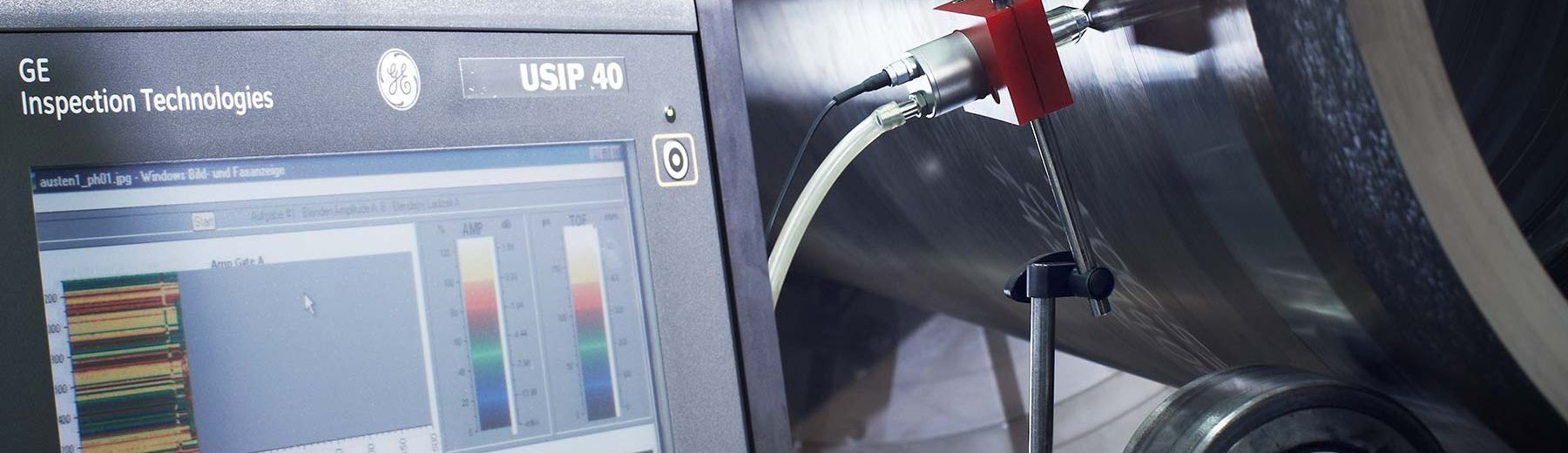
Ultrasound test
Category: Physical and non-destructive test method.
Objective: Ultrasound testing is an acoustic procedure used to detect internal and external material flaws, such as those found in welded seams, castings, semi-finished items or pipe conduits. The detection of external (surface) flaws is mainly of importance when dealing with components where the other surface, normally on the inside, is inaccessible. A distinction is made between the reflected-sound and sound-transmission techniques.
Test principle: A couplant (such as paste, gel, water or oil) is applied to the surface of the work piece. An oscillating probe is then used to generate an ultrasonic impulse (of between 0.5 and 25 MHz), which is transferred to the work piece via the couplant.
The various contact surfaces of the test material (cracks laminations, back-wall etc.), which possess different levels of sound resistance, send ultrasonic impulses back the oscillating probe, which now functions as a receiver. The impulse-echo procedure then uses the time lapse between sending and receiving to calculate the distance covered.
Evaluation/Result: The test results are logged in accordance with currently-applicable standards and/or customer specifications.
We would be pleased to answer your questions on the subjects of stainless steel casting, centrifugal casting and composite casting, along with the machining of stainless steel and the manufacture of components to your own precise specifications, including items for decanter construction, shipbuilding, engine manufacture and much else besides.
Just call us on
+49 (0)2195 671-0
infonothing@kuhn-edelstahl.com